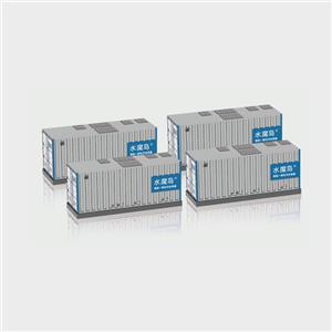
Biological Aerated Filter

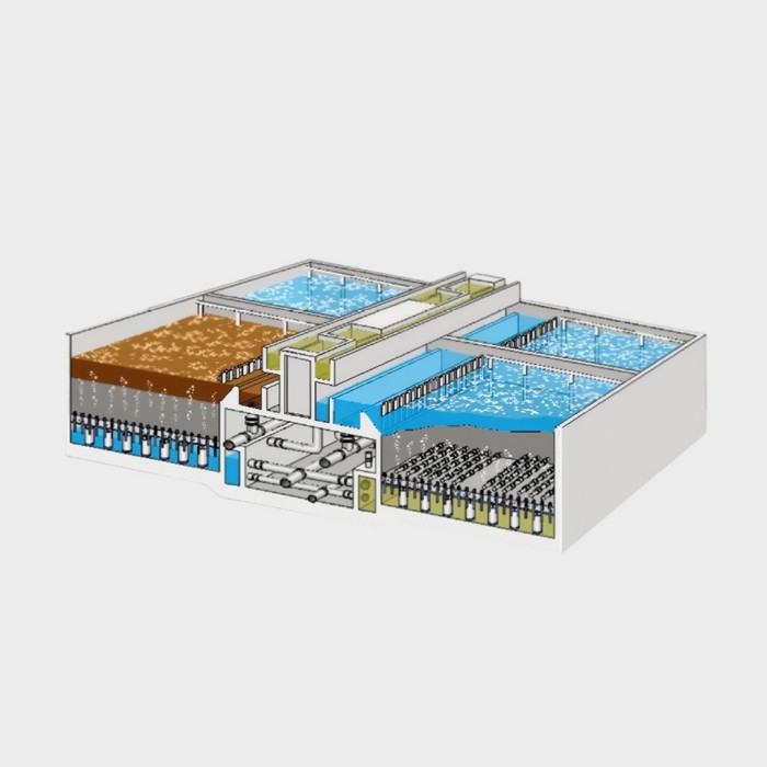
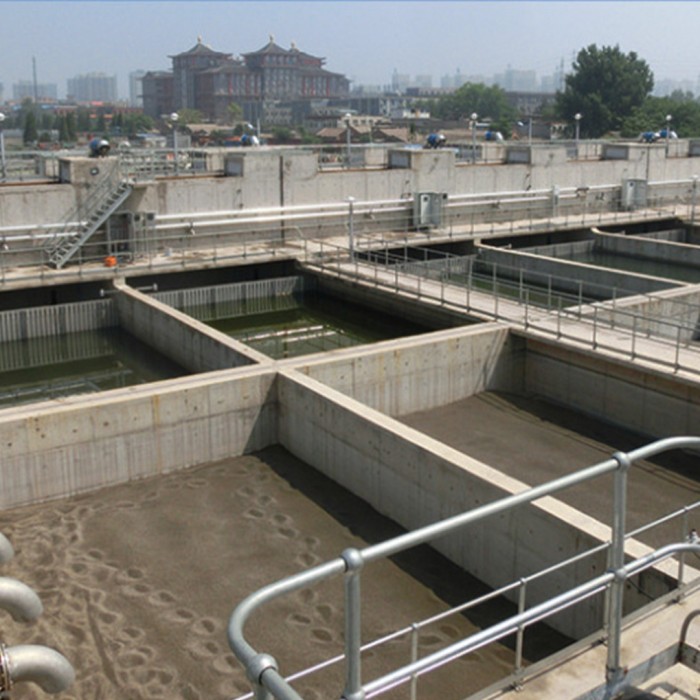
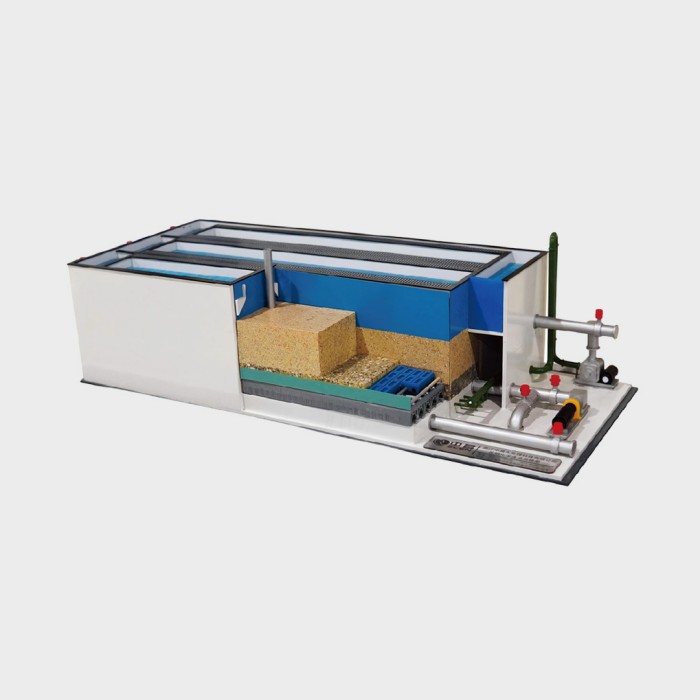
The Biological Aerated Filter (BAF) is an aerobic or anoxic biological reactor using granular filter media for fixed biofilm. It integrates biological contact oxidation and suspended solids filtration into a single unit, effectively removing SS, CODcr, BOD₅, NH₃-N, TN, TP, AOX (hazardous substances), as well as hardness, turbidity, and color from water. It is suitable for municipal wastewater, industrial wastewater, advanced treatment for water reuse, and pretreatment of polluted raw water sources. Due to its numerous advantages unmatched by other processes, BAF has been widely adopted both domestically and internationally in recent years.
Process Features
Optimized process flow: Combines biological contact oxidation and filtration in one unit, eliminating the need for secondary clarifiers and sludge return.
High loading capacity: Hydraulic loading up to 5–38 m³/m²·h; BOD₅ loading up to 3–5 kg BOD₅/m³·d; NH₃-N loading up to 1–1.5 kg NH₃-N/m³·d.
Compact footprint: Typically only 30–40% of conventional processes; allows for a compact and aesthetically pleasing plant layout.
Superior effluent quality: Exceeds Class I national discharge standards with clear, visually appealing effluent – ideal for water reuse.
Low investment: Optimized BAF design can save approximately 20–30% in capital investment compared to conventional processes.
Low energy & operating costs: Aeration system utilization up to 30%; air-to-water ratio of only 3–4:1 for municipal wastewater treatment.
Excellent system stability: Strong shock load resistance, minimal impact from climatic temperature variations, and easy system restart.
Superior modular design: Facilitates management and allows for phased construction and future expansion.
High automation: Backwash and aeration systems can be fully automated via PLC, enabling convenient operation and easy maintenance.
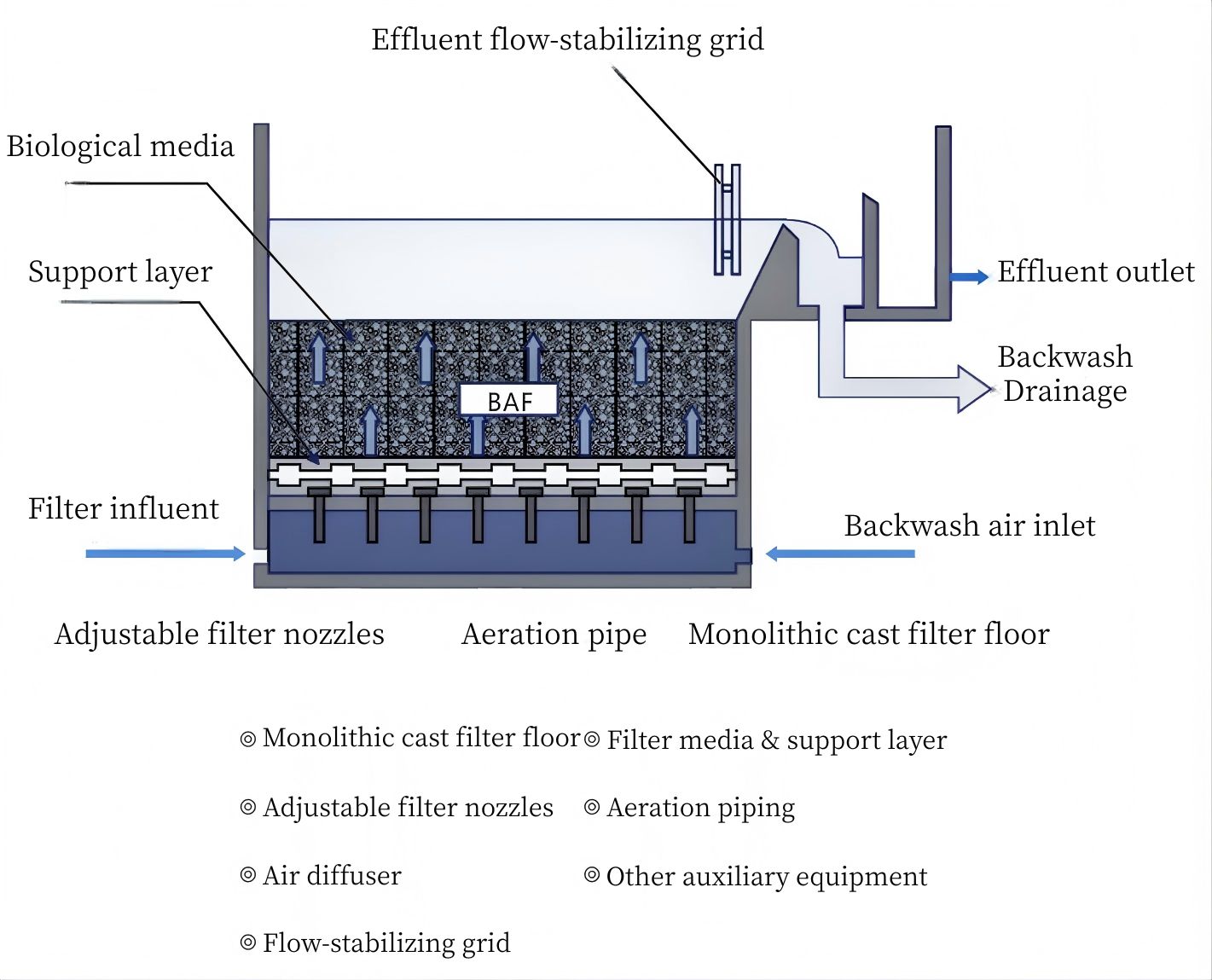
Types & Applications
Different BAF configurations are available to meet various treatment objectives:
BAF-C – for removal of CODcr, BOD₅, SS, etc.
BAF-C/N – simultaneous organic removal and nitrification.
BAF-N – for nitrification and NH₃-N removal.
BAF-DN – for denitrification and TN removal (can be pre- or post-positioned).
BAF-DN+P – for simultaneous denitrification and chemical phosphorus removal.
Our company provides complete equipment, auxiliary components, and installation accessories to ensure safe, stable, and reliable system operation. We also offer process design, equipment installation guidance, system commissioning, and trial operation services for biological filter systems.
Process Features
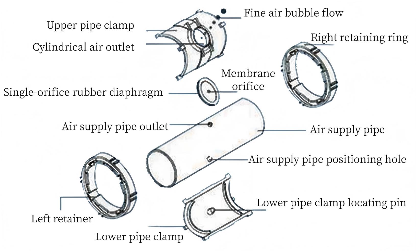
In the BAF process, oxygen required by microorganisms is supplied through aeration systems consisting of blowers, air diffusers, and a network of interconnected piping that forcibly introduces air into the system. The single‑orifice rubber diaphragm aerator (also known as an air diffuser) addresses common issues found in other aerators, such as uneven large bubbles, low oxygen transfer efficiency, and susceptibility to clogging. The single‑orifice rubber diaphragm aerator offers excellent air diffusion performance, producing fine, uniform bubbles with a wide distribution range. It is resistant to clogging by debris, withstands compression from filter media, and is easy to install — making it an ideal air diffusion device for BAF systems (stainless steel aeration piping is also available).
Single‑Orifice Rubber Diaphragm Aerator – Technical Specifications
| Specification | Air Flow Rate | Pressure Drop | System Oxygen Transfer Rate | Installation Density | Aeration Pipe O.D. |
| φ62.5 × 46.5 mm | 0.15–0.45 m³/h | ≤1500 Pa | 30% | 30–49 units/m² | D25, D32 |
Structure & Assembly Method
Pre‑drill air outlet holes (through‑holes) and positioning holes (blind holes) on the air supply branch pipe. The axes of the two holes should overlap and lie on the pipe diameter.
Insert the single‑orifice rubber diaphragm into the groove beneath the air outlet hole on the upper pipe clamp.
Install the upper and lower pipe clamps onto the air supply branch pipe, ensuring that the diaphragm hole on the upper clamp aligns with the air outlet hole on the branch pipe, and that the locating pin on the lower clamp inserts precisely into the positioning hole on the branch pipe.
Slip the left and right retaining rings over the ends of the cylindrical assembly formed by the upper and lower clamps, then rotate them to lock and secure the single‑orifice rubber diaphragm aerator onto the air supply branch pipe.
Ancillary Components for Use with Single‑Orifice Rubber Diaphragm Aerator
Air distributor
Stainless steel union
Connector / adapter
Sealing ring (EPDM rubber)
Air supply branch pipe (FRPP, SS304, ABS)
Plug
Support bracket
Stainless steel expansion bolt