Flap Valve

Flap Valve
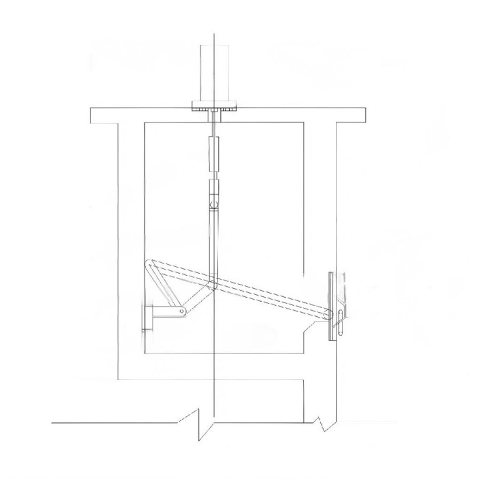
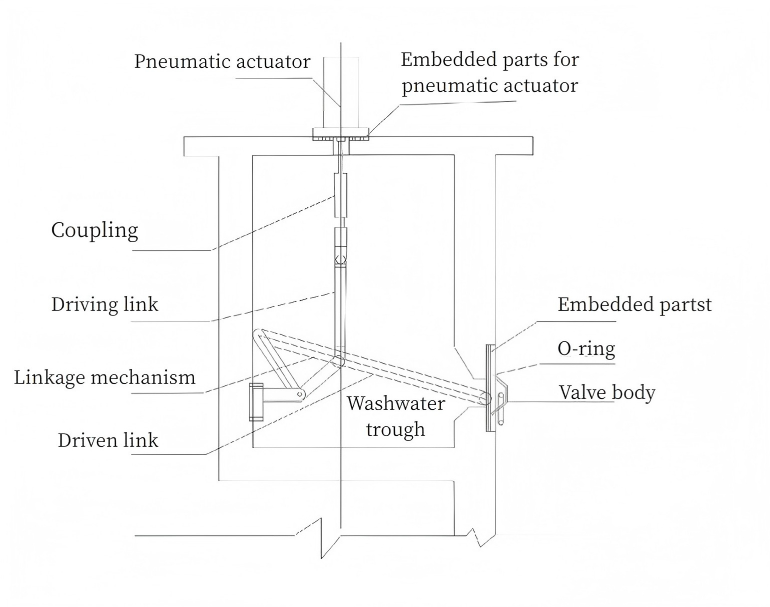
The flap valve mainly consists of four components: cylinder, drive crank arm, flap frame, and flap plate. All components are manufactured from high‑strength stainless steel.
Working Principle
Compressed air is used as the power source. The cylinder piston rod drives the crank arm and connecting rods to rotate the valve stem 0–90° for opening and closing.
Installation Method
The valve body is installed directly in the pre‑cast opening on the filter wall, approximately 10–20 cm above the filter media surface. The drive crank arm is mounted on the drainage channel wall, and the cylinder is installed on the drainage channel cover plate.
Parameter Table
| Performance Parameter Table Of Pneumatic Flap Valve | |||
| Parameter | Unit | Value | |
| Maximum Working Head | M | 5 | |
| pH Value Of Working Medium | pH | 5 - 10 | |
| Maximum Leakage (per meter length) | L/ (m·min) | ≤0.65* | |
| Operating Temperature | 5°C - 60°C | ||
| Applicable medium | Sewage / Clean water | ||
| Standard Materials | Valve body | Stainless steel | |
| Drive crank arm | Stainless steel | ||
| Sealing | Rubber | ||
| Other parts | Stainless steel/Carbon steel (hot-dip galvanized) | ||
| Note: The maximum leakage allowance in the national standard is 1.25L (m·min) | |||
| Performance Parameter Table Of Pneumatic Flap Valve | |
| Control Signal | 24V DC (20V AC) switching signal (on‑off) |
| Feedback Signal | Fully closed / half‑open / fully open position switching signals |
| Temperature | -20℃ - 80℃ |
| Electrical Interface | 1/2" internal pipe thread |
| Specifications | |||
| No. | Water outlet size | Number of cylinders | Number of valve plates |
| 1 | 2.8m * 0.15m | 1 | 2 |
| 2 | 3.2m * 0.15m | 1 | 2 |
| 3 | 3.2m * 0.2m | 1 | 2 |
| Air Supply Parameters | |
| Supply air pressure | 0.4 – 0.7 MPa |
| Ambient temperature | -20℃ to 80℃ |
| Air consumption | 0.1–0.7 min (air consumption per stroke) |
Product Tag: